After opening the GNS3 client and starting nodes, we primarily access the remote virtual devices with a console connection. This console connection is either Telnet, VNC, or SPICE. A console connection covers our requirement for physical access to virtual devices, but today, most administrative tasks are carried out with a link to the network management interface .
I define the GNS3 server as remote if the
gns3serverprocess is not running on the host operating system. I consider the GNS3 VM remote because thegns3serverprocess runs on a guest operating system (Ubuntu).
Management Interface
Most network virtual appliances allocate the first network interface as the management interface. The management interface may allow protocols (e.g., SSH, HTTPS, NETCONF) to install, manipulate, and delete the network device’s configuration. For example, the following is just a sample of network virtual appliances that utilize HTTP(S) for device configuration:
- Cisco Adaptive Security Device Manager (ASDM) for the Cisco ASAv
- Web Interface for the Palo Alto Networks VM-Series Firewall
- Configuration utility (Web UI) for the F5 BIG-IP LTM VE
- Web Admin (GUI) for the FortiGate VM
Management Network
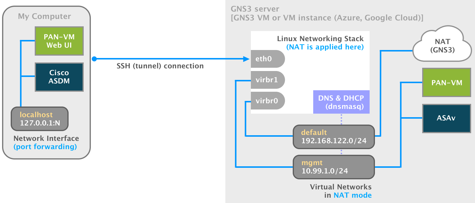
Each management interface needs to be attached to a software bridge for connectivity. The Linux bridge is a software L2 device similar to a physical bridge device. It can forward traffic between virtualization guests, the host OS, and possibly off-node via the host OS’s physical network interfaces.
When we use the NAT node with GNS3 on Linux, we use the virbr0 Linux bridge. The bridge was created with the installation of libvirt
. It’s a component of the libvirt default virtual network. Let’s delve further into the details of the network before we create our management network.
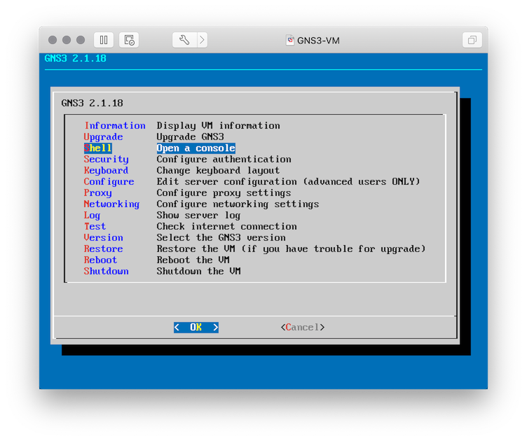
- Our first task is to log in to a shell. Choose from one of the following:
GNS3 VM
- Start the GNS3 VM with the VMware application.
- From the VMware console:
- Select OK and ⏎ to get to the menu.
- Select Shell and ⏎.
Alternatively, we can connect via SSH with the username/password of gns3/gns3.
ssh gns3@<gns3_vm_ip>
Google Compute Engine
There are many ways to deploy GNS3 with Google Compute Engine (GCE), but we will use https://github.com/mweisel/gcp-gns3server as the reference for this post.
- Sign in to the GCP Console .
- Select the GNS3 project.
- Activate the Google Cloud Shell.
- List the Google Compute Engine instances.
gcloud compute instances list
- Start the
gns3serverinstance (if required).
gcloud compute instances start gns3server --zone <gce_zone> --quiet
- SSH into the
gns3serverinstance.
gcloud compute ssh gns3server --zone <gce_zone>
- Add yourself to the
libvirtgroup.
sudo gpasswd -a $USER libvirt
- Log out and back in for the new group membership to take effect.
exit
gcloud compute ssh gns3server --zone <gce_zone>
Microsoft Azure
There are also many ways to deploy GNS3 with Microsoft Azure, but we will use https://github.com/mweisel/azure-gns3server as the reference for this post.
- Sign in to the Azure Portal .
- Launch the Azure Cloud Shell (Bash).
- List the Azure instances.
az vm list -d -g gns3-resources -o table
- Start the
gns3serverinstance (if required).
az vm start -g gns3-resources -n gns3-server
- List the IP addresses for the Azure instances.
az vm list-ip-addresses -g gns3-resources -n gns3-server -o table
- SSH into the
gns3serverinstance.
ssh <PublicIPAddress>
- Add yourself to the
libvirtgroup.
sudo gpasswd -a $USER libvirt
- Log out and back in for the new group membership to take effect.
exit
ssh <PublicIPAddress>
- After we log into a shell, list all the libvirt virtual networks on the host.
virsh net-list --all
output:
Name                 State      Autostart     Persistent
----------------------------------------------------------
default              active     yes           yes
- Display more information about the
defaultvirtual network.
virsh net-info default
output:
Name:           default
UUID:           68142228-ab29-445e-8bcd-4ea334546217
Active:         yes
Persistent:     yes
Autostart:      yes
Bridge:         virbr0
As noted earlier, the virbr0 Linux bridge is associated with the default network.
- We can get more detailed information by dumping the network definition in its XML form.
virsh net-dumpxml default
output:
<network>
  <name>default</name>
  <uuid>68142228-ab29-445e-8bcd-4ea334546217</uuid>
  <forward mode='nat'>
    <nat>
      <port start='1024' end='65535'/>
    </nat>
  </forward>
  <bridge name='virbr0' stp='on' delay='0'/>
  <mac address='52:54:00:11:84:43'/>
  <ip address='192.168.122.1' netmask='255.255.255.0'>
    <dhcp>
      <range start='192.168.122.2' end='192.168.122.254'/>
    </dhcp>
  </ip>
</network>
The following details of the default virtual network are revealed:
- The virtual network operates in NAT mode.
- DHCP services are enabled for guests connected to the virtual network.
- Show information about the
virbr0bridge.
brctl show virbr0
output:
bridge name    bridge id            STP enabled    interfaces
virbr0         8000.525400118443    yes            virbr0-nic
- Display the IPv4 address for the
virbr0bridge interface.
ip addr show virbr0 | awk '/inet/ { print $2 }'
output:
192.168.122.1/24
The IPv4 address assigned to the interface is also the gateway address for nodes (guests) connected to the virtual network.
We should now have a better understanding of how all the network pieces fit together, so let’s create a new libvirt virtual network. It will be the management network for our GNS3 devices.
- Install the
nanotext editor (if required).
sudo apt update && sudo apt install nano
- Create the XML definition file with a text editor.
nano net-mgmt.xml
Add the following content:
<network>
  <name>mgmt</name>
  <forward mode='nat'>
    <nat>
      <port start='1024' end='65535'/>
    </nat>
  </forward>
  <bridge name='virbr1' stp='on' delay='0'/>
  <ip address='10.99.1.1' netmask='255.255.255.0'>
    <dhcp>
      <range start='10.99.1.128' end='10.99.1.254'/>
    </dhcp>
  </ip>
</network>- ⌃ +
o(Save) the file. - ⏎ to confirm.
- ⌃ +
x(exit) thenanotext editor.
- As a safety measure, validate the libvirt XML for compliance.
virt-xml-validate net-mgmt.xml
- Define the
mgmtnetwork from the libvirt XML file.
virsh net-define net-mgmt.xml
- Again, list all the libvirt virtual networks on the host.
virsh net-list --all
output:
Name                 State      Autostart     Persistent
----------------------------------------------------------
default              active     yes           yes
mgmt                 inactive   no            yes
The mgmt network is listed, but completing the configuration requires more steps.
- Start the inactive
mgmtnetwork.
virsh net-start mgmt
- Set the
mgmtnetwork to autostart with the libvirtd service on boot.
virsh net-autostart mgmt
- Verify the
mgmtnetwork is active and enabled for autostart.
virsh net-list --all
output:
Name                 State      Autostart     Persistent
----------------------------------------------------------
default              active     yes           yes
mgmt                 active     yes           yes
- We can display information about the
mgmtnetwork as we did with thedefaultnetwork.
virsh net-info mgmt
output:
Name:           mgmt
UUID:           91c49b86-faaa-4b8a-a0d5-f3d00e5b2511
Active:         yes
Persistent:     yes
Autostart:      yes
Bridge:         virbr1
- Display the network definition in XML.
virsh net-dumpxml mgmt
output:
<network>
  <name>mgmt</name>
  <uuid>91c49b86-faaa-4b8a-a0d5-f3d00e5b2511</uuid>
  <forward mode='nat'>
    <nat>
      <port start='1024' end='65535'/>
    </nat>
  </forward>
  <bridge name='virbr1' stp='on' delay='0'/>
  <mac address='52:54:00:64:b4:80'/>
  <ip address='10.99.1.1' netmask='255.255.255.0'>
    <dhcp>
      <range start='10.99.1.128' end='10.99.1.254'/>
    </dhcp>
  </ip>
</network>- Show information about the
virbr1bridge.
brctl show virbr1
output:
bridge name    bridge id            STP enabled    interfaces
virbr1         8000.52540064b480    yes            virbr1-nic
- DHCP for libvirt uses the dnsmasq
program. Verify the list of process(es) for the
mgmtnetwork.
pgrep -af 'libvirt/dnsmasq/mgmt.conf'
output:
1691 /usr/sbin/dnsmasq --conf-file=/var/lib/libvirt/dnsmasq/mgmt.conf --leasefile-ro --dhcp-script=/usr/lib/libvirt/libvirt_leaseshelper
1692 /usr/sbin/dnsmasq --conf-file=/var/lib/libvirt/dnsmasq/mgmt.conf --leasefile-ro --dhcp-script=/usr/lib/libvirt/libvirt_leaseshelper
- Verify the NAT rules for iptables have been added for the
mgmtnetwork.
sudo iptables --list --numeric --table nat
output:
Chain PREROUTING (policy ACCEPT)
target     prot opt source               destination
DOCKER     all  --  0.0.0.0/0            0.0.0.0/0            ADDRTYPE match dst-type LOCAL

Chain INPUT (policy ACCEPT)
target     prot opt source               destination

Chain OUTPUT (policy ACCEPT)
target     prot opt source               destination
DOCKER     all  --  0.0.0.0/0           !127.0.0.0/8          ADDRTYPE match dst-type LOCAL

Chain POSTROUTING (policy ACCEPT)
target     prot opt source               destination
RETURN     all  --  10.99.1.0/24         224.0.0.0/24
RETURN     all  --  10.99.1.0/24         255.255.255.255
MASQUERADE  tcp  --  10.99.1.0/24        !10.99.1.0/24         masq ports: 1024-65535
MASQUERADE  udp  --  10.99.1.0/24        !10.99.1.0/24         masq ports: 1024-65535
MASQUERADE  all  --  10.99.1.0/24        !10.99.1.0/24
RETURN     all  --  192.168.122.0/24     224.0.0.0/24
RETURN     all  --  192.168.122.0/24     255.255.255.255
MASQUERADE  tcp  --  192.168.122.0/24    !192.168.122.0/24     masq ports: 1024-65535
MASQUERADE  udp  --  192.168.122.0/24    !192.168.122.0/24     masq ports: 1024-65535
MASQUERADE  all  --  192.168.122.0/24    !192.168.122.0/24
MASQUERADE  all  --  172.17.0.0/16        0.0.0.0/0

Chain DOCKER (2 references)
target     prot opt source               destination
RETURN     all  --  0.0.0.0/0            0.0.0.0/0
GNS3
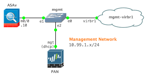
The Linux OS-level networking configuration is set, so we will proceed to the next phase. My project includes both a Cisco ASAv and Palo Alto Networks (PAN) VM node. Each node will have its first network interface connected to the management network we just created. Although I’m simply using a Cisco ASAv and PAN VM device for my example, the following configuration pattern applies to most other virtual network devices in GNS3.
- Open the GNS3 client application.
- Create a new project.
- Drag a Cloud node from the Devices toolbar to the workspace.
- Right-click the Cloud node and select Configure.
- On the Ethernet interfaces tab:
- Enable Show special Ethernet interfaces.
- Click the drop-down menu and select virbr1.
- Click the Add button.
- Select the Misc. tab and enter
mgmt-virbr1in the Name field. - Click the OK button to save the configuration and close the window.
- Drag an Ethernet switch (Dynamips) node from the Devices toolbar to the workspace.
- Right-click the Ethernet switch node, select Change hostname and enter
mgmtin the Hostname field. - Click the OK button to save the configuration and close the window.
- Click the Add a link icon in the Devices toolbar.
- In the workspace, click the Ethernet switch node and select the Ethernet0 interface.
- Click the Cloud node and select the virbr1 interface to link the objects.
- Click the Add a link icon in the Devices toolbar to escape the mode.
- Drag a Cisco ASAv node from the Devices toolbar to the workspace.
- Click the Add a link icon in the Devices toolbar.
- In the workspace, click the Cisco ASAv node and select the Management0/0 interface.
- Click the Ethernet switch node and select the Ethernet1 interface to link the objects.
- Click the Add a link icon in the Devices toolbar to escape the mode.
- Drag a Palo Alto Networks (PAN) VM node from the Devices toolbar to the workspace.
- Click the Add a link icon in the Devices toolbar.
- In the workspace, click the Palo Alto Networks (PAN) VM node and select the management interface.
- Click the Ethernet switch node and select the Ethernet2 interface to link the objects.
- Click the Add a link icon in the Devices toolbar to escape the mode.
Palo Alto Networks (PAN) VM
The device-level PAN configuration is automagically set (for management) thanks to DHCP and PAN-OS defaults.
- Right-click the PAN VM node and select Start.
- Right-click the PAN VM node and select Console.
- Log in with a username/password of
admin/admin. - Verify the DHCP client for the management interface grabbed an IPv4 address from dnsmasq on the Linux host.
show interface management
output:
-------------------------------------------------------------------------------
Name: Management Interface
Link status:
  Runtime link speed/duplex/state: 1000/full/up
  Configured link speed/duplex/state: auto/auto/auto
MAC address:
  Port MAC address 0c:5f:c1:c7:75:00

Ip address: 10.99.1.212
Netmask: 255.255.255.0
Default gateway: 10.99.1.1
Ipv6 address: unknown
Ipv6 link local address: fe80::e5f:c1ff:fec7:7500/64
Ipv6 default gateway:
-------------------------------------------------------------------------------
- Optionally, verify the PAN management interface has Internet connectivity.
ping count 5 host www.gns3.com
Cisco ASAv
My project uses the Cisco ASAv 9.9(2) with ASDM 7.9(2), so I complete the following tasks in the CLI:
- Create the gns3 user.
- Configure the m0/0 interface.
- Set the default route for the management security zone.
- Configure SSH (Secure Shell).
- Enable Cisco Adaptive Security Device Manager (ASDM) access.
- Save the configuration.
- Right-click the Cisco ASAv node and select Start.
- Right-click the Cisco ASAv node and select Console.
- Set the configuration.
en
conf t
username gns3 password gns3 privilege 15
int m0/0
 nameif management
 security-level 100
 ip addr 10.99.1.10 255.255.255.0
 no shut
 exit
route management 0 0 10.99.1.1
aaa authentication ssh console LOCAL
aaa authorization exec LOCAL auto-enable
ssh version 2
ssh timeout 60
ssh key-exchange group dh-group14-sha1
ssh scopy enable
ssh 0 0 management
domain-name example.com
crypto key generate rsa usage-keys label SSHKEYS modulus 1024
asdm image boot:/asdm-79247.bin
http server enable 8443
http 0.0.0.0 0.0.0.0 management
end
copy run start
- Optionally, verify the ASAv management interface has Internet connectivity.
ping 8.8.8.8
SSH Local Port Forwarding
We have accomplished quite a bit, but we haven’t answered the most crucial question: how do we open an application (e.g., web browser, Cisco ASDM) on our local computer that connects to a remote device running on the GNS3 VM (server)?
SSH port forwarding serves as a wrapper around arbitrary TCP traffic. It is sometimes called tunneling because the SSH connection provides a secure tunnel through which another TCP/IP connection may pass.
The three types of port forwarding are local, remote, and dynamic. For this post, we are only concerned with local port forwarding. Local port forwarding redirects one port on the client to one port on the server. Essentially, you’re saying, “Take a port on the SSH server and make it local to my client.”
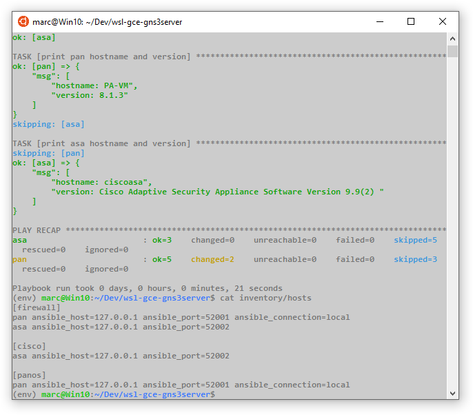
- Identify the IPv4 address and port number for the service running on the remote device.
PAN VM
show interface management | match 'Ip addr'
show system services
show netstat listening yes numeric-ports yes | match :443
HTTPS is listening on the standard TCP/443 port for the logical address of the management interface.
Cisco ASAv
show int management ip brief
show run http
show asp table socket
HTTPS (for ASDM) is listening on the TCP/8443 port for the management interface’s logical address.
- Choose a local port to use for the forwarding.
On Unix-like systems, TCP ports below 1024 are reserved for system use. Only root can bind to these ports. As an unprivileged user, we can attach the local end of our SSH port forwarder to any port above 1024. Microsoft operating systems do not implement privileged ports. Anyone can bind to any open port on the system.
I prefer to choose a number from the ephemeral port range (49152 - 65535). I will use the following assignment for my devices:
- PAN VM: TCP/
52001 - Cisco ASAv: TCP/
52002
Username and SSH Private Key (Google Compute Engine and Microsoft Azure)
Skip this section if using the GNS3 VM. The GNS3 VM uses password authentication for SSH.
If using either gcp-gns3server or azure-gns3server , the SSH server on the Ubuntu VM instance is configured only to accept public key authentication. We are tasked with identifying the user and downloading the associated SSH private key file from the Cloud Shell instance.
Google Compute Engine
- Sign in to the GCP Console .
- Select the GNS3 project.
- Activate the Google Cloud Shell.
- Identify the user for the SSH private key file.
echo $USER
- Display the fully qualified file path for the SSH private key file.
ls $HOME/.ssh/google_compute_engine
- Click the ⋮ (vertical ellipsis) icon in the upper-right corner of the Google Cloud Shell toolbar.
- Select Download file.
- Enter the fully qualified file path from the output of the previous
lscommand. - Click the DOWNLOAD link.
Microsoft Azure
- Sign in to the Azure Portal .
- Launch the Azure Cloud Shell (Bash).
- Identify the user for the SSH private key file.
echo $USER
- Click the Upload/Download files icon on the Azure Cloud Shell toolbar.
- Select Download.
- Enter
/.ssh/id_rsain the required field. - Click the Download button.
Linux and macOS
SSH key pairs for Unix-like systems are usually stored in the local SSH directory ($HOME/.ssh). The directory is created when OpenSSH client programs are first used.
- Create the local SSH directory (if required).
if [ ! -d "$HOME/.ssh" ]; then; mkdir -pm 700 $HOME/.ssh; fi
- Move (and rename) the SSH private key file to the local SSH directory.
# GCE
mv -v $HOME/Downloads/google_compute_engine $HOME/.ssh/google-gns3server
# Azure
mv -v $HOME/Downloads/id_rsa $HOME/.ssh/azure-gns3server
- Secure the SSH private key file permissions.
# GCE
chmod -v 0600 $HOME/.ssh/google-gns3server
# Azure
chmod -v 0600 $HOME/.ssh/azure-gns3server
OpenSSH
We use the OpenSSH client with:
- macOS
- Linux
- OpenSSH for Windows 10
- Portable OpenSSH
- Linux via Windows Subsystem for Linux (WSL)
Use the `-L’ flag to tell the client to activate local port forwarding.
ssh -L <local_ip>:<local_port>:<remote_mgmt_ip>:<remote_mgmt_port> gns3_server_ip_or_hostname
I also like to add a couple of flags when local port forwarding. The -N flag tells SSH not to execute a remote command on the server, including creating a terminal. The -f flag tells SSH to put itself in the background.
ssh -fNL <local_ip>:<local_port>:<remote_mgmt_ip>:<remote_mgmt_port> gns3_server_ip_or_hostname
GNS3 VM
Authenticate with the username and password of gns3 to the GNS3 VM with IP address 192.168.200.240, and forward port 443 (HTTPS) on the PAN VM management interface (10.99.1.212) to the local port 52001 on my computer:
ssh -fNL 127.0.0.1:52001:10.99.1.212:443 [email protected]
Google Compute Engine
Authenticate with user marc (and associated SSH private key file) to the remote GNS3 server with public IP address 35.199.147.244, and forward port 8443 (HTTPS) on the Cisco ASAv management interface (10.99.1.10) to the local port 52002 on my computer:
ssh -i $HOME/.ssh/google-gns3server -fNL 127.0.0.1:52002:10.99.1.10:8443 [email protected]
Disconnect the SSH local port forward session
Because we put each SSH session in the background, we need to terminate each session manually when we’re finished with the port forward. The following terminates both sessions in a single command:
pkill -f '127.0.0.1:5200[1-2]'
PuTTY
PuTTY is the most popular SSH client for the Windows platform. It’s a great alternative if you prefer to use a GUI instead of the command line-based SSH tools.
PEM → PPK Private Key Format Conversion
Skip this section if using the GNS3 VM. The GNS3 VM uses password authentication for SSH.
The SSH private key is in the .pem format from the Cloud Shell instances for either Google Compute Engine or Microsoft Azure. The key needs to be converted to the .ppk format before use in the PuTTY application.
- Open the PuTTY Key Generator application.
- Click the Load button for the Load an existing private key file action.
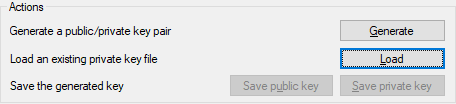
- Select All Files (.) from the file extension drop-down list.

-
Navigate to and select the private key file:
google_compute_enginefor Google Compute Engineid_rsafor Microsoft Azure
-
Click the Open button.
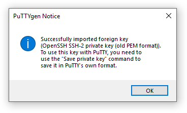
-
Click the OK button to close the PuTTYgen Notice window.
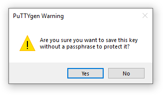
- Click the Save private key button for the Save the generated key action.
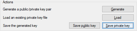
- Click the Yes button to acknowledge and close the PuTTYgen Warning window.
-
Save private key as:
google-gns3serverfor Google Compute Engineazure-gns3serverfor Microsoft Azure
-
Click the Save button.
-
Close the PuTTY Key Generator application.
GNS3 VM
Authenticate with the username and password of gns3 to the GNS3 VM with IP address 192.168.200.240 and:
- Forward port 443 on the PAN VM management interface to the local port 52001 on my computer
- Forward port 8443 on the Cisco ASAv management interface to the local port 52002 on my computer
- Open the PuTTY application.
- Go to Session.
- Enter
192.168.200.240in the Host Name (or IP address) field.

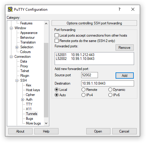
- Go to Connection → SSH → Tunnels.
- Enter
52001in the Source port field. - Enter
10.99.1.212:443in the Destination field. - Click the Add button to add the entry.
- Enter
52002in the Source port field. - Enter
10.99.1.10:8443in the Destination field. - Click the Add button to add the entry.
- Click the Open button to be prompted for the login credentials and establish the session.
Microsoft Azure
Authenticate with user mweisel (and associated SSH private key file) to the GNS3 server hosted at Microsoft Azure with the public IP address 13.66.209.19 and:
- Forward port 443 on the PAN VM management interface to the local port 52001 on my computer
- Forward port 8443 on the Cisco ASAv management interface to the local port 52002 on my computer
- Open the PuTTY application.
- Go to Session.
- Enter
13.66.209.19in the Host Name (or IP address) field.
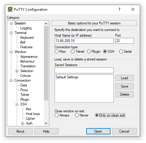
- Go to Connection → SSH → Auth.
- Click the Browse button for the Authentication parameters section.
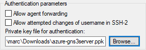
- Navigate to and select the azure-gns3server private key file.
- Click the Open button.
- Go to Connection → SSH → Tunnels.
- Enter
52001in the Source port field. - Enter
10.99.1.212:443in the Destination field. - Click the Add button to add the entry.
- Enter
52002in the Source port field. - Enter
10.99.1.10:8443in the Destination field. - Click the Add button to add the entry.
- Click the Open button to be prompted for the username and establish the session.
There’s No Place Like 127.0.0.1
Verify ports are open and in a listening state on our local computer.
Windows
Run the following command in a PowerShell console:
Get-NetTCPConnection -LocalAddress 127.0.0.1 -LocalPort 52001,52002 | Format-Table Local*,State
output:
LocalAddress LocalPort  State
------------ ---------  -----
127.0.0.1        52002 Listen
127.0.0.1        52001 Listen
macOS
Run the following command in a terminal:
netstat -anf inet | grep '5200[1-2]'
output:
tcp4       0      0  127.0.0.1.52002        *.*                    LISTEN
tcp4       0      0  127.0.0.1.52001        *.*                    LISTEN
Linux
Run the following command in a terminal:
ss -tnlp | grep '5200[1-2]'
output:
LISTEN   0         128               127.0.0.1:52001            0.0.0.0:*        users:(("ssh",pid=1595,fd=4))
LISTEN   0         128               127.0.0.1:52002            0.0.0.0:*        users:(("ssh",pid=1603,fd=4))
Point applications to localhost
And now, for the moment of truth:
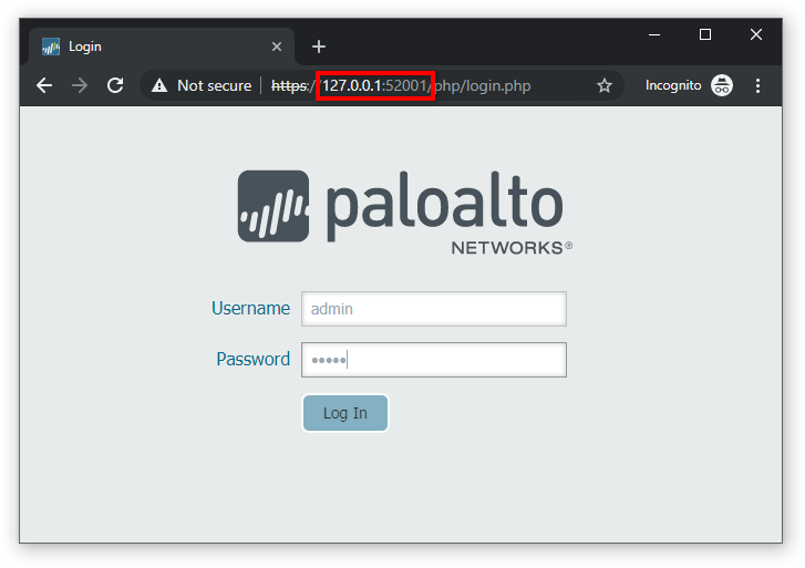
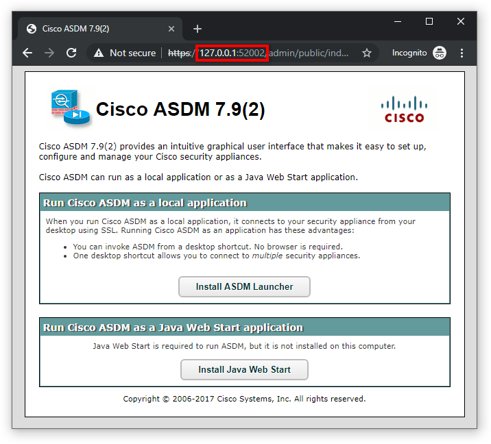
- Open a web browser and enter
https://127.0.0.1:52001in the URL address bar to connect to the remote PAN VM device’s Web UI. - Open a new browser window (or tab) and enter
https://127.0.0.1:52002in the URL address bar to connect to the ASDM page of the remote Cisco ASAv device. - Ansible/Nornir: Set each device’s specific host variables (e.g., IPv4 address, port).